Introduction
In Europe, the Machinery Directive, which is a legal act, establishes the necessary tasks for new machines to meet health and safety requirements. This means that Manufacturers are obliged to construct their machines such that they are safe. In practise, this means that designers should perform a risk assessment to identify potential hazards design in the resulting measures.
When a hazard is identified, the risk should be estimated and evaluated. Risk is a product of the extent of damage and the probability of occurrence i.e. how bad multiplied by how likely, figure 1.
Figure 1: Calculation of RISK
In order to presume compliance with the Machinery Directive, harmonised standards can be used. A standard is an agreed, repeatable way of doing something. They contain technical specifications or other precise criteria designed to be used consistently as a rule, guideline, or definition and they are developed by interested parties (Manufacturers, users, test bodies, occupational health and safety authorities, governments etc.). A standard becomes “Harmonised” when it is published in the Official Journal which is kind of an official gazette (periodical publication) which can easily found online for free. EN ISO 12100 specifies principles of risk assessment and risk reduction and it states that if the risk evaluation shows that measures are necessary to reduce the risk, the 3-step method must be used.
The Three-Step Method involves in the order given:
- Safe design; This could be for example, mechanical design or materials used etc. This is the first and most important step and also the most effective approach.
- Risk reduction by means of technical protective measures; This could be for example safety light curtains, safety lasers scanners, Interlocks etc.. When the effect of a protective measure is dependent on the correct functioning of a control system, the term functional safety is used.
- User information; If safe design and protective measures do not provide the required risk reduction, the user shall receive additional warning, for example, acoustic/optical warning or operating procedures, personal protective equipment etc.
Safety Functions
Concentrating on step 2 of the three step method which is about the application of protective measures. This is a subject has had much media coverage over the years and involves defining safety functions that specify how risks are reduced using protective measures. The harmonised standard EN ISO 13849 can be used to assist with this and a typical safety function can be represented as a combination of safety related parts of control systems (SRP/CS), figure 2.
Figure 2: Diagrammatic presentation of a safety function
The drive element is only included as part of the safety function if their failure may lead to a hazard, for example suspended axes. However, they should be designed according to “good engineering practises”.
EN ISO 13849 provides a list of safety functions/characteristics along with details of applicable international standards, which designers can use to achieve the necessary safety. Below we shall look at the topic “Prevention of Unexpected start-up”.
Prevention of Unexpected Start-Up
EN ISO 13849 refers to this subject and as well as referring to EN ISO 12100 and IEC 60204, it refers to the standard ISO 14118, entitled “Safety of machinery – Prevention of start-up”.
EN ISO 14118 cover the subject of keeping a machine in a stopped condition whilst people are located in danger zones and applies to all types of energy sources. However, with respect to the start-up of a machine by normal, automatic operation (like pressing an operator starting a process for example), the standard says that it this type of start-up should not be considered as unintended but rather “unexpected” from the point of the view of the operator. It also says that prevention of this type of start-up involves the use of safeguarding measures, which implies the application of a safety function.
Application of Reset and Restart
On power up or after a protective device has issued a stop command one way of starting up a machine is to activate a manual reset and then activate a restart. Another way to start a machine up is to use additional protective devices that constantly detect the presence of persons in hazard zones. Examples of the latter are trapped key systems or the use of Electro Sensitive Protective Equipment (ESPE’s) such as safety laser scanners or safety light curtains to detect people, figure 3.
Figure 3: Preventing a Start
However, as convenient and cost effective it is to apply safe presence detection, this approach is not always practical due to the size or shape of the area that needs to be monitored.
If it is not possible to detect a person then we are back to the well tried and tested method of firstly activating a reset and then activating a restart. EN ISO 13849 covers these two functions and again refers to sections of EN ISO 12100 and IEC 60204.
There are some important criteria when implementing the manual reset such as it being a manual, separate and deliberate action and that signal processing is required to detect the falling edge etc. However, one of the most important aspects of the command device is that its location should be:
- Outside the hazard zone, and
- In a position such that it is possible to completely oversee the hazard zone
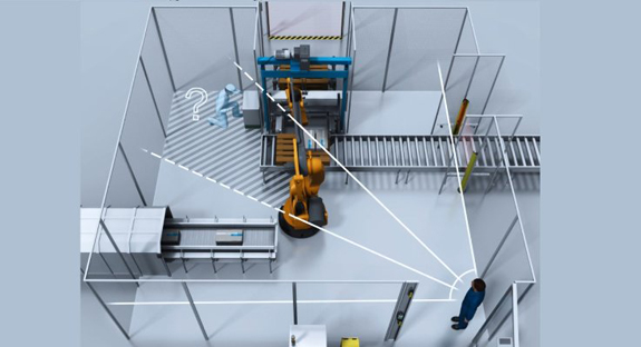
This is to ensure that nobody is inside the hazard zone. This criterion is important but there are times safe presence detection is not possible AND it is not possible to position a reset device such that the whole hazard zone is visible. EN ISO 13849 states that in this case a special procedure is required.
One particular solution that EN ISO 13849 gives as an example is to use a second actuator (Second reset button). The principle of this solution is that there are two buttons, which force the operator to check blind spots. In order to reset the machine, both buttons must be activated within a limited time of each other. This is a useful solution but can be tricky to program and could also be open to manipulation or error and a full risk assessment should be performed to determine the residual risk.
Alternative Solutions
There are also other solutions available for this task, which can offer advantages over purely sequential approaches. An example of such a solution, which is kind of a hybrid of the two methods mentioned above, is to use RFID technology which enforces a mandatory safety procedure to provide the protection for operating personnel.
By developing this solution, it can be made such that it is only possible to enter a hazardous area after a machine has stopped safely. In addition, to reset the machine, the operator is forced to check blind spots of the hazardous area whilst also being safely detected so that nobody else can reset the machine, figure 4.
Figure 4: Alternative Solution
By incorporating safety RFID switches into a safe control system in the form of an electronic key mounted on the exterior of the access door with additional modules located at suitable positions a workflow could be adopted:
Workflow
- To start the safe procedure the operator removes the key from the module on the gate and keep hold of it.
- A stop is then initiated and the door opens when it is safe to do so.
- The operator can the enter the hazardous area taking the key with them to complete any work.
- When work is completed, the operator must follow the procedure which has been defined by risk assessment in order to enable the machine to be reset.
Since the operator must carry the key with them, the solution provides safe presence detection, preventing anything or anyone else resetting the machine. It also enforces a safe procedure for checking blind spots to ensure no one is present inside the hazardous area – This could be for example, to present the key to an additional module in a blind spot to force them to check that area before exiting and putting the key back into the gate module within a certain time period. Even if the operator did not take the key with them, it would require another person to:
- Find the key: Diagnostics can ensure that it cannot be left inside the module outside the cell
- Know the procedure: They would need to know where the second module is and what to do (and within a certain time period)
- Willingly reset a dangerous machine knowing there is a person inside
This solution would not work for every machine and depends on a good risk assessment plus safety related application software (SRASW) to be developed according to EN ISO 13849-1. This would require the designer to produce a comprehensive functional safety specification, from which SRASW can be produced together with a method for verification and validation (EN ISO 13849-2).
Summary
In summary, prevention of unexpected start-up is a safety function in its own right and there are harmonised standards, which can assist such as EN ISO 13849 and EN ISO 12100. There are different solutions available to make your machine safe such as trapped keys, reset/restart buttons, ESPE’s and unique RFID solutions can be developed. However, regardless of the solution used, “Prevention of Unexpected start-up” is a safety function and therefore the required performance level has to be defined and, more importantly, achieved. The Safety of machines remains the responsibility of the machine builder and a full risk assessment is required to identify hazards and reduce risks accordingly. If you need help with any of your applications then please feel free to contract SICK.
[LinkedIn | Dr Martin Kidman, PhD FS Engineer | TÜV Rheinland – link to the original article]


