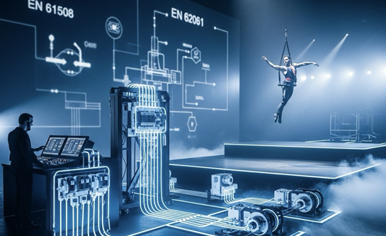
In the captivating world of modern theatre, concert production, and live events, the line between art and engineering is increasingly blurred. Soaring aerial performances, colossal set pieces gliding silently across the stage, and stages that transform in the blink of an eye are no longer the stuff of fantasy but the nightly reality of the entertainment industry. This magic, however, is underpinned by a complex and powerful array of machinery—winches, hoists, lifts, turntables, and automated trusses. The failure of any single component can have catastrophic consequences, endangering performers, crew, and audiences alike. Consequently, the discipline of functional safety has become paramount.
At the heart of functional safety are international standards that provide a rigorous framework for designing, implementing, and maintaining safety-related systems. Two of the most significant standards are EN 61508 and EN 62061. While related, they serve different purposes and present different methodologies. EN 61508 is the foundational, or “umbrella,” standard for functional safety across all industries. EN 62061 is a sector-specific standard derived from it, tailored explicitly for the safety of machinery control systems.
For the designer, manufacturer, or integrator of stage machinery, the choice between—or the combined understanding of—these two standards is not merely an academic exercise. It is a critical decision that impacts design philosophy, component selection, verification processes, documentation, and ultimately, the provable safety and legal compliance of their equipment.
This article provides an exhaustive, in-depth comparison of EN 61508 and EN 62061, framed specifically within the context of the entertainment industry. We will dissect their philosophies, explore their core concepts, and contrast their methodologies for risk assessment, hardware architecture, software development, and lifecycle management. Through a detailed case study of a typical stage flying system, we will illustrate the practical application of both standards, highlighting their respective strengths and weaknesses. By the end of this analysis, readers will have a comprehensive understanding of which standard is most appropriate for their specific needs and how to navigate the complex but essential world of functional safety to ensure that the show, above all else, can go on safely.
1 Introduction to Functional Safety and the Safety Lifecycle
1.1 What is Functional Safety?
Before comparing the two standards, it is essential to grasp the concept they both serve: functional safety. Traditional safety might involve guards, fences, or physical barriers to prevent access to a hazard. Functional safety, however, is the part of the overall safety of a system that depends on that system operating correctly in response to its inputs.
Consider a large, automated stage lift. A physical barrier (traditional safety) prevents someone from falling into the pit when the lift is lowered. Functional safety, on the other hand, is what prevents the lift from moving unexpectedly while performers are on it, or what stops it from crashing at the top of its travel. It relies on a Safety-Related Control System (SRCS)—a system of sensors, logic solvers, and actuators—to detect a potentially dangerous condition and execute a pre-defined safe action. Functional safety is active, not passive.
In the entertainment industry, this is ubiquitous. It is the system that ensures a 500 kg video wall doesn’t drop, that a performer hoist has a reliable emergency stop, and that a revolving stage brakes safely in its designated position.
1.2 Defining Key Terminology: Hazard, Risk, and Tolerable Risk
The language of safety standards is precise.
- Harm: Physical injury or damage to the health of people. In our context, this can range from minor injuries to multiple fatalities.
- Hazard: A potential source of harm. For a stage winch, hazards include gravity (the suspended load), kinetic energy (a moving load), and electricity.
- Hazardous Event: An event that can cause harm, such as the unintended release of a brake on a winch.
- Risk: A combination of the probability of occurrence of harm and the severity of that harm. A winch brake failing over an empty stage carries a lower risk than the same failure over a group of performers.
The goal of functional safety is not to eliminate risk entirely—an impossible task—but to reduce it to a Tolerable or Acceptable Risk level. This is a level of risk that is accepted in a given context based on the current values of society. We accept the small risk of travelling by air because the societal and economic benefits are deemed to outweigh it. Similarly, the artistic and commercial value of a spectacular stage effect must be weighed against its residual risks. The standards provide a structured way to achieve and demonstrate that this tolerable risk level has been reached.
1.3 The Concept of Safety Integrity Level (SIL)
The Safety Integrity Level (SIL) is the core concept in both standards. It is a discrete level (from 1 to 4) indicating the degree of risk reduction provided by a safety function. A higher SIL corresponds to a greater risk reduction.
- SIL 1: For mitigating relatively low-level risks.
- SIL 2: A common level for standard industrial machinery risks.
- SIL 3: For high-risk scenarios where failure could result in serious injury or death for one or more persons. Much of the safety-critical machinery in the entertainment industry, especially that involving flying performers or heavy overhead loads, targets SIL 2 or SIL 3.
- SIL 4: For catastrophic, societal-level risks (e.g., nuclear power plant shutdown systems). It is virtually never encountered in machinery or stage applications.

Crucially, SIL is a property of a safety function, not of a component or a system as a whole. A complex automation controller doesn’t have “a SIL”. However, its safety function to prevent unintended movement might be specified to meet SIL 3. This function is realised by a combination of inputs, logic, and outputs. The SIL specifies three key properties for that function:
- Architectural Constraints: Requirements on the structure of the system (e.g., redundancy).
- Probability of Dangerous Failure: A quantitative target for the reliability of the function.
- Systematic Capability: Measures to avoid and control errors throughout the entire design and engineering process.
1.4 The Overarching Safety Lifecycle Model
Both EN 61508 and EN 62061 are built around a Safety Lifecycle. This is a structured engineering process, often depicted as a V-model, that covers a safety system from conception to decommissioning. Its purpose is to ensure that safety is considered at every stage and that all activities are planned, documented, and verified.
The main phases of the safety lifecycle include:
- Concept Phase: Defining the equipment and its scope.
- Hazard and Risk Analysis: Identifying everything that could go wrong and evaluating the associated risks.
- Allocation of Safety Functions: Defining the safety functions needed to mitigate the identified risks and assigning a target SIL to each.
- Realisation Phase (Design & Engineering):
- Writing the safety requirements specification.
- Designing the hardware and software of the safety system.
- Verifying that the design meets the SIL requirements (through analysis and calculation).
- Installation, Commissioning, and Validation:
- Installing the equipment correctly.
- Testing the safety functions to ensure they work as specified in the real world (Validation).
- Operation, Maintenance, and Repair:
- Using the equipment as intended.
- Performing regular proof tests and maintenance to ensure safety integrity is maintained.
- Managing repairs and modifications.
- Modification and Decommissioning:
- Safely managing any changes to the system.
- Safely taking the system out of service at the end of its life.
This lifecycle model is the backbone of both standards. It enforces a rigorous, documented process, moving away from an ad-hoc approach to safety and towards a provable, auditable methodology.
2 The Progenitor: EN 61508
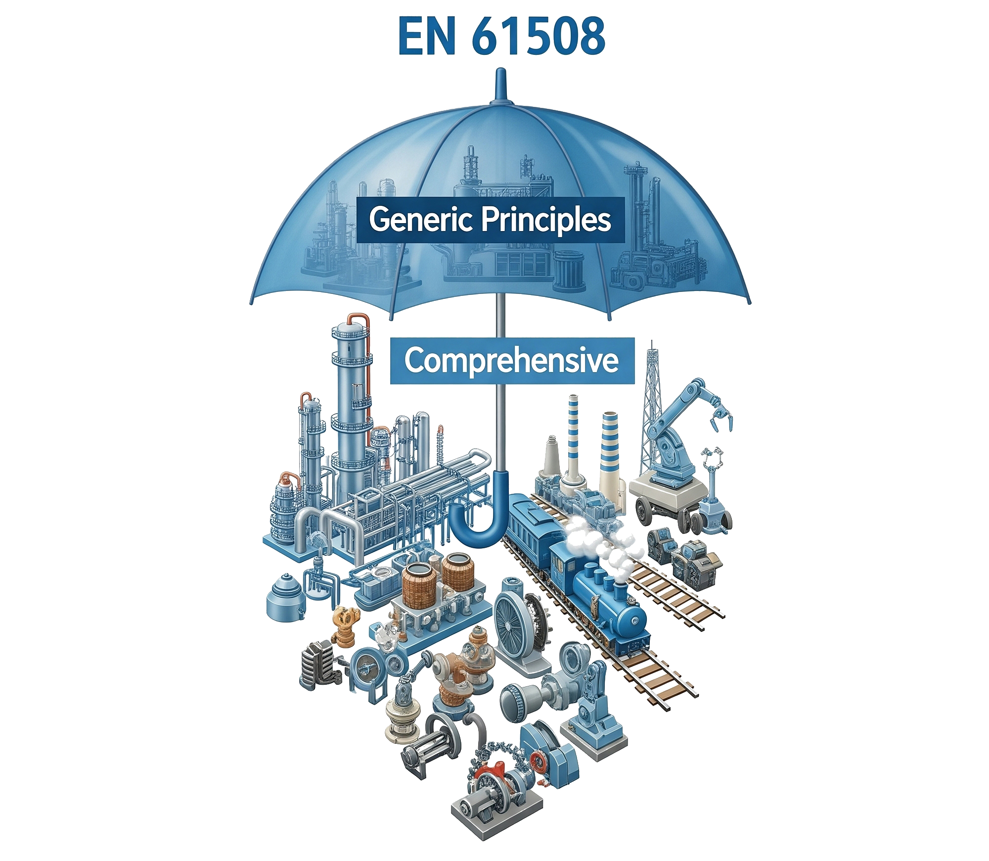
2.1 Scope and Philosophy: The “Umbrella” Standard
IEC 61508 (adopted in Europe as EN 61508) is titled “Functional safety of electrical/electronic/programmable electronic safety-related systems (E/E/PE).” It is a basic safety standard, meaning it is intended to be generic and applicable across any industry where E/E/PE systems are used for safety purposes. It was originally driven by the needs of the process industries (chemical, oil & gas), but its principles are universal.
Its philosophy is to provide a complete, all-encompassing framework for any conceivable safety system. It makes no assumptions about the type of machinery or process being controlled. Because it is generic, it is necessarily detailed, complex, and often abstract. It is the “first principles” document from which other, more focused standards are derived. Think of it as the constitution for functional safety; other standards are the specific laws for different jurisdictions.
For the entertainment industry, using EN 61508 directly means applying these first principles to your specific stage machinery without the interpretive layer of a sector standard. This provides maximum flexibility but also places a significant burden of interpretation and justification on the engineering team.
It is, therefore, not a recommended standard to use on stage machinery.
2.2 Structure of the Standard (Parts 1-7)
EN 61508 is a substantial document, published in seven parts:
- Part 1: General requirements: Lays out the overall safety lifecycle, the management of functional safety, and the documentation framework. It introduces the core concepts like SILs.
- Part 2: Requirements for E/E/PE safety-related systems: This is the heart of the hardware requirements. It details how to design hardware to meet a target SIL, introducing concepts like Hardware Fault Tolerance and Safe Failure Fraction.
- Part 3: Software requirements: Provides a highly detailed and rigorous lifecycle model for the development of safety-related software. It links development techniques and verification measures to the required SIL.
- Part 4: Definitions and abbreviations: A glossary of the precise terminology used throughout the standard.
- Part 5: Examples of methods for the determination of safety integrity levels: Gives guidance and examples on how to perform a risk assessment and assign SILs.
- Part 6: Guidelines on the application of Parts 2 and 3: Provides further guidance and rationale for the hardware and software requirements.
- Part 7: Overview of techniques and measures: Contains extensive tables of various engineering techniques (e.g., for fault detection, software design) and recommends their use based on the target SIL.
This structure demonstrates the standard’s comprehensive nature. It attempts to cover every facet of a safety project, from management and documentation (Part 1) to hardware (Part 2) and software (Part 3) in exhaustive detail.
2.3 Core Concepts of EN 61508
To understand the difference between the two standards, one must first understand the key technical concepts defined in EN 61508.
2.3.1 Safety Functions and Target SIL
As mentioned, the process begins with identifying risks and defining safety functions to control them. EN 61508 provides several methods for determining the required SIL, including qualitative risk graphs, LOPA (Layer of Protection Analysis), and quantitative analysis. The output is a target SIL (1, 2, or 3) for each safety function. This target becomes the primary input for the design process.
2.3.2 Hardware Safety Integrity: Architectural Constraints
This is a critical area and a major point of difference with EN 62061. EN 61508 specifies that to claim a certain SIL for a hardware design, you must satisfy architectural constraints. This is a check to ensure the system is robust enough to tolerate faults, independent of the calculated failure rates of its components. It primarily revolves around two concepts: Hardware Fault Tolerance (HFT) and Safe Failure Fraction (SFF).
2.3.2.1 Hardware Fault Tolerance (HFT)
HFT is a measure of redundancy.
-
- HFT = 0: The system has no redundancy. A single dangerous fault can lead to the loss of the safety function. This is a single-channel architecture (e.g., one contactor).
-
- HFT = 1: The system can tolerate one dangerous fault and still perform its safety function. This typically requires two channels (e.g., two contactors in series with monitoring). This is often described as a 1oo2 (one-out-of-two) or 2oo2 (two-out-of-two) architecture.
- HFT = 2: The system can tolerate two dangerous faults. This requires three channels.
2.3.2.2 Safe Failure Fraction (SFF) and Route 1H
For a component or subsystem, the SFF is the percentage of its total failures that are “safe” or “dangerous but detected”. A safe failure is one that does not compromise the safety function (e.g., a contactor failing open). A dangerous detected failure is one that would compromise safety, but a diagnostic mechanism detects it and triggers a safe state (e.g., a monitoring circuit detects that a contactor’s contacts have welded shut and trips the main breaker).
The formula is:
Where:
- λSD = rate of Safe Detected failures
- λSU = rate of Safe Undetected failures
- λDD = rate of Dangerous Detected failures16
- λDU = rate of Dangerous Undetected failures
EN 61508 (Part 2) provides a table (known as Route 1H) that links the required SIL to the minimum HFT based on the SFF of the subsystem.
| Safe Failure Fraction (SFF) | HFT = 0 | HFT = 1 | HFT = 2 |
|---|---|---|---|
| < 60% | Not allowed | SIL 1 | SIL 2 |
| 60% to < 90% | SIL 1 | SIL 2 | SIL 3 |
| 90% to < 99% | SIL 2 | SIL 3 | SIL 4 |
| >= 99% | SIL 3 | SIL 4 | SIL 4 |
To meet SIL 3 with a non-redundant (HFT=0) element, you would need to prove it has an SFF of over 99%, which is extremely difficult. This table effectively drives the designer towards using redundancy (increasing HFT) for higher SILs. The challenge for a stage machinery builder is that calculating the SFF requires a detailed Failure Modes, Effects, and Diagnostics Analysis (FMEDA) for every component, which is a highly specialised and data-intensive task.
2.3.2.3 Proven in Use and Route 2H
EN 61508 provides an alternative path, Route 2H, for demonstrating hardware architectural constraints. This route is based on demonstrating reliability through extensive historical operating data—”proven in use.” It requires a huge amount of high-quality data on operating hours, failures, and demand rates for the exact component in a similar application and environment. For the often bespoke or low-volume nature of entertainment machinery, collecting sufficient data to satisfy the stringent requirements of Route 2H is often impractical.
2.3.3 Quantifying Random Hardware Failures: PFDavg and PFHD
Beyond architectural constraints, the standard requires a probabilistic calculation to show that the safety function meets its target reliability. There are two modes of operation:
- Low Demand Mode: The safety function is only called upon infrequently (e.g., less than once per year). This is typical of emergency shutdown systems in process plants. The metric used is the Average Probability of Failure on Demand (PFDavg).
- High Demand or Continuous Mode: The safety function is used frequently (more than once per year) or is continuously active. The metric is the Probability of a Dangerous Failure per Hour (PFHD).
For virtually all stage machinery (e.g., emergency stops, overspeed protection, brake control), the system is in continuous mode, so the PFHD is the relevant metric.
| SIL | Target PFHD (failures per hour) |
|---|---|
| 1 | ≥10−6 to <10−5 |
| 2 | ≥10−7 to <10−6 |
| 3 | ≥10−8 to <10−7 |
| 4 | ≥10−9 to <10−8 |
Calculating the PFHD involves complex reliability modelling, often using Markov models or simplified formulas that account for the failure rates of all components, diagnostic coverage, common cause failures, and proof test intervals.
2.3.4 Systematic Safety Integrity: Systematic Capability (SC)
Hardware can fail randomly, but safety systems can also fail due to errors made during specification, design, or manufacturing. These are systematic failures. EN 61508 introduces the concept of Systematic Capability (SC). Every component used in a safety function has an SC rating (SC 1, SC 2, SC 3, or SC 4), which reflects the rigour of the process used to develop it.
A key rule is that the SIL of a safety function cannot exceed the lowest SC of any component used to implement it. You cannot build a SIL 3 function using a component that was only developed with SIL 2-compliant processes (i.e., has a rating of SC 2), no matter how much redundancy you add. This ensures that quality and rigour are built-in, not just added on.
2.3.5 The Rigours of Software Development (Part 3)
EN 61508 Part 3 is legendary for its rigour. It defines a detailed V-model for software development and mandates specific techniques, measures, and documentation for each phase based on the target SIL. For SIL 3, it requires extremely strict methods, including formal methods, detailed module testing, integration testing, and validation, all performed by independent teams. Writing bespoke, fully compliant
SIL 3 software from scratch under EN 61508 is a monumental undertaking, typically reserved for developers of safety PLCs or other off-the-shelf safety devices.
2.4 Applying EN 61508 in an Entertainment Context: A Conceptual View
Imagine you are building a control system for a performer flying system and decide to use EN 61508 directly. You would need to:
-
- Manage the project strictly according to the safety lifecycle in Part 1.
- Define the safety function “Prevent unintended payload drop” and determine its target SIL is 3.
- Design the hardware (brakes, contactors, monitoring circuits). For each element, you would need to:
- Perform a FMEDA to calculate its SFF.
- Use the SFF and the table in Part 2 to determine the required HFT (likely HFT=1, i.e., dual channels).
- Source components that have a certified Systematic Capability of SC 3.
- If writing any custom software (e.g., in a standard PLC), follow the punishingly strict SIL 3 requirements of Part 3.
- Calculate the total PFHD for the entire safety function and show it is less than 10−7.
- Produce a comprehensive safety case document justifying every decision and calculation.</span
The complexity, especially around the SFF calculation and software development, makes this a daunting task for a typical stage machinery manufacturer. This very complexity is what led to the development of sector-specific standards like EN 62061.
3 The Specialist: EN 62061
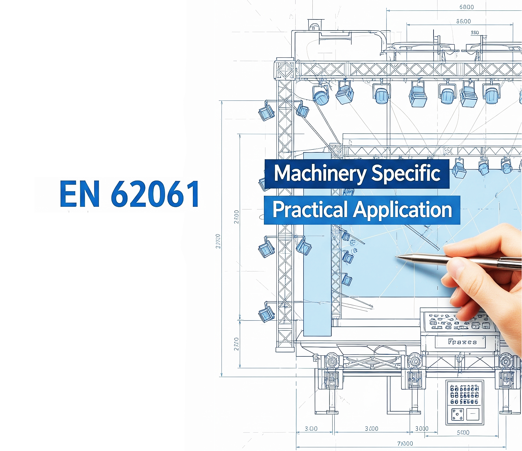
3.1 Scope and Philosophy: Safety for Machinery Control Systems
EN 62061, titled “Safety of machinery – Functional safety of safety-related electrical, electronic and programmable electronic control systems,” is a direct implementation of EN 61508 for the machinery sector. Its scope is narrower and more focused. It does not apply to the entire machine, only to its Safety-Related Control System (SRCS).
Its core philosophy is to take the fundamental principles of EN 61508 and make them more practical and accessible for machinery builders. It achieves this by:
- Providing a more prescriptive and simplified methodology.
- Replacing abstract concepts like SFF with more intuitive parameters.
- Providing pre-defined architectural structures.
- Aligning its terminology and concepts with other key machinery safety standards, particularly ISO 13849-1.
It is designed to be used as part of a wider risk assessment process for a machine, typically conducted according to EN ISO 12100 (“Safety of machinery – General principles for design”).
3.2 Relationship with EN 61508 and ISO 13849-1
- Relationship to EN 61508: EN 62061 is a subordinate standard. It states that compliance with its requirements also demonstrates compliance with the relevant requirements of EN 61508. It acts as an interpretation layer, translating the generic principles of its parent standard into concrete rules for machinery control systems.
- Relationship to ISO 13849-1: This is another crucial machinery safety standard that runs in parallel to EN 62061. ISO 13849-1 uses a different metric, Performance Level (PL), with levels ‘a’ through ‘e’. While the methodologies differ, PLs and SILs are broadly comparable (e.g., PL e is comparable to SIL 3, PL d to SIL 2). For a long time, designers could choose which standard to follow. The latest versions of both standards have been harmonised to work together more smoothly. EN 62061 now explicitly includes methods for integrating subsystems designed according to ISO 13849-1 into an overall SIL calculation. For a stage machinery builder, it is highly likely they will use both standards: ISO 13849-1 for simpler parts of the control system and EN 62061 for more complex, programmable systems.
3.3 The EN 62061 Workflow
The process under EN 62061 is more linear and prescriptive than the more theoretical framework of EN 61508.
3.3.1 Risk Assessment and SIL Determination
EN 62061 provides its own specific risk graph for assigning a SIL. This is a key simplification. The user evaluates four parameters:
- Severity of Injury (Se): From minor to serious/fatal.
- Frequency and Duration of Exposure (Fr): How often are people near the hazard?
- Probability of Occurrence of a Hazardous Event (Pr): How likely is the event to happen without the safety function?
- Probability of Avoiding or Limiting Harm (Av): Is it possible to get out of the way?
These parameters are combined in a matrix to directly yield a required SIL (1, 2, or 3) for the safety function. This is a much more straightforward process than the open-ended methods suggested in EN 61508.
3.3.2 Defining the Safety-Related Control System (SRCS) and its Safety Functions
The process starts by clearly specifying the required safety functions (e.g., Safe Torque Off, Safe Stop 1, Safe Brake Control). The entire system that executes this function is the SRCS.
3.3.3 Subsystem-Based Architecture
This is a cornerstone of the EN 62061 approach. An SRCS is broken down into a series of connected subsystems. A typical architecture is Input -> Logic -> Output.
- Input Subsystem: An emergency stop button, a light curtain, a limit switch.
- Logic Subsystem: A safety PLC, a safety relay.
- Output Subsystem: A contactor, a motor drive with a safe torque off (STO) input, a solenoid valve for a hydraulic brake.
Each of these subsystems is analysed independently, and their results are then combined. This modular approach maps very well to how control systems are actually built.
3.3.4 Hardware Safety Integrity: Simplified Architectural Constraints
EN 62061 does away with the complex SFF calculation. Instead, it provides four pre-defined Basic Subsystem Architectures (A, B, C, D), which are derived from the categories in ISO 13849-1.
- Architecture A: Single channel, no diagnostics (HFT=0). Similar to Category B.
- Architecture B: Single channel with testing (HFT=0). Similar to Category 2.
- Architecture C: Dual channel, monitored (HFT=1). Similar to Category 3.
- Architecture D: Dual channel, monitored, with enhanced diagnostics (HFT=1). Similar to Category 4.
The standard specifies the maximum SIL that can be claimed by a subsystem based on its architecture. For example, to achieve SIL 3, you typically need Architecture D. This provides a clear, prescriptive path for the designer: “To get SIL 3, I need a dual-channel, cross-monitored design.”
3.3.5 Quantifying Performance: The PFHD Calculation
This is the most significant simplification offered by EN 62061. It provides a straightforward, block-based method for calculating the PFHD of each subsystem. The calculation uses parameters that are more readily available from component manufacturers:
- Mean Time to Dangerous Failure (MTTFd): The average time a component will operate before a dangerous failure occurs. This replaces the complex failure mode analysis needed for SFF. Manufacturers of safety components (like switches, relays, drives) must provide this data.
- Diagnostic Coverage (DC): The percentage of dangerous failures that are detected by the diagnostic mechanisms. For the pre-defined architectures, typical DC values are given (e.g., 60% for Cat 2, 99% for Cat 4).
- Common Cause Failures (CCF): Failures that can affect multiple channels of a redundant system simultaneously (e.g., a power surge, vibration). EN 62061 uses a simple checklist and scoring system (the Beta-factor method) to quantify the mitigation of CCFs. A score of 65 or more is required for most redundant systems.
The standard provides simplified formulas for each architecture (A, B, C, D) to calculate the subsystem’s PFHD.
Once the PFHD of each subsystem (Input, Logic, Output) is calculated, they are simply added together to get the total PFHD for the entire safety function:
This total must then be less than the target limit for the required SIL. This “sum-of-parts” method is vastly more intuitive and manageable for a machinery builder than the integrated reliability modelling often required by EN 61508.
3.3.6 Systematic and Software Requirements
EN 62061 still requires management of systematic failures. It uses the same Systematic Capability (SC) concept from EN 61508. However, for software, it offers a more pragmatic approach.
Instead of the highly onerous Part 3 of EN 61508, EN 62061 has its own section on software. It makes a key distinction:
- Limited Variability Language (LVL): This refers to configuration or simple function block programming, as is typical in safety PLCs. The requirements for LVL software are significantly less demanding than for full programming.
- Full Variability Language (FVL): This is traditional text-based programming (e.g., C++, Structured Text). The requirements here are still very strict and point back towards EN 61508-3, but the standard acknowledges that most machinery safety functions can be achieved using LVL.
This distinction is crucial for the entertainment industry. A stage automation system is typically programmed by connecting pre-certified function blocks in a safety PLC. This is LVL, making the software verification and validation process under EN 62061 far more achievable.
3.4 Advantages of the Sector-Specific Approach for Stage Machinery
For the builder of a stage winch, turntable, or lift, the advantages of using EN 62061 are clear:
- Clarity: The standard provides a step-by-step recipe to follow.
- Accessibility: The concepts (MTTFd, DC, Architectures A-D) are more intuitive for control engineers.
- Practicality: The data required (MTTFd, B10d) is what safety component manufacturers provide in their datasheets. The complex FMEDA is not required of the end-user.
- Software Realism: The LVL classification makes compliance for systems built with safety PLCs manageable.
- Integration: It aligns well with ISO 13849-1, allowing for a mix-and-match approach that reflects real-world system design.
4. Head-to-Head Comparison: EN 61508 vs. EN 62061
This section directly contrasts the two standards across key areas, with a focus on the impact for a stage machinery context.
4.1 Scope and Applicability
- EN 61508: Generic, basic safety standard. Applies to any E/E/PE safety-related system in any industry. It can be applied to the design of the components themselves (e.g., developing a new safety PLC).
- EN 62061: Sector-specific standard for machinery control systems (SRCS). It is intended for the application of safety components into a system, not the development of those components.
- Entertainment Industry Relevance: EN 62061’s scope is a perfect fit for the work of most stage automation companies, who are integrating off-the-shelf safety components into a control system for a specific machine. EN 61508 would be the relevant standard for the company that manufactures the SIL 3-rated safety drive or PLC being used.
4.2 Risk Assessment and SIL Assignment
- EN 61508: Provides general guidance and several possible methods (qualitative, quantitative, LOPA). This offers flexibility but requires more expertise and justification from the user.
- EN 62061: Provides one specific, calibrated risk graph. It is prescriptive, less ambiguous, and easier to apply consistently.
- Entertainment Industry Relevance: The EN 62061 graph is well-suited to machinery risks and is easier for project teams and safety assessors to use and review. Its parameters (Severity, Frequency, etc.) are directly applicable to assessing the risk of a moving set piece or performer hoist.
4.3 Hardware Architecture and Design
- EN 61508: Requires proof of architectural robustness via HFT and SFF (Route 1H) or extensive historical data (Route 2H). This is powerful but abstract and data-intensive. The designer must derive the architecture from first principles.
- EN 62061: Provides pre-defined Subsystem Architectures (A, B, C, D) which are prescriptive. The designer chooses an architecture that meets the SIL requirement. The complex SFF calculation is replaced by the simpler MTTFd and DC parameters.
- Entertainment Industry Relevance: This is arguably the biggest practical difference. A stage engineer can think in terms of “I need a dual-channel, monitored brake circuit” (Architecture C), which is far more intuitive than “I need to calculate the SFF of my brake contactor and its monitoring circuit to prove it’s >90%.”
4.4 Probabilistic Calculations (PFHD)
- EN 61508: The formulas for calculating PFHD are presented in an appendix and can be complex, often requiring reliability modelling skills. It deals with the devices as a whole.
- EN 62061: Provides simplified, specific formulas for each subsystem architecture. The total PFHD is a simple sum of the subsystem values. The block-based approach is much simpler.
- Entertainment Industry Relevance: The “sum-of-parts” method in EN 62061 is ideal for machinery integrators. They can get the PFHD value for the safety PLC from its manual, calculate the PFHD for their chosen ESTOP and contactors, and simply add them up. This dramatically lowers the barrier to performing a correct quantitative analysis.
4.5 Software Development and V&V
- EN 61508: Part 3 sets an extremely high bar for any custom software, regardless of complexity. It does not distinguish between writing an operating system and configuring a few logic blocks.
- EN 62061: Makes the critical distinction between Limited Variability Language (LVL) and Full Variability Language (FVL). The requirements for LVL, which covers the vast majority of machinery application programming, are far more manageable.
- Entertainment Industry Relevance: This makes EN 62061 vastly more practical. Stage automation is almost always done by configuring pre-certified blocks in a safety PLC. Applying the full weight of EN 61508-3 would be prohibitively expensive and time-consuming. EN 62061 provides a compliant path that is proportionate to the actual risk.
4.6 Data Requirements and Component Selection
- EN 61508: Requires knowledge of all failure modes (λS, λD) to calculate SFF. This data is rarely available from component manufacturers, except for complex devices that have been specifically certified to EN 61508.
- EN 62061: Requires MTTFd and Diagnostic Coverage (DC). This data (or related data like B10d from which MTTFd can be calculated) is now routinely provided by manufacturers of safety-rated machinery components.
- Entertainment Industry Relevance: An engineer building a stage winch can find the necessary data for their chosen light curtain, safety relay, and drive in the product manuals. They do not need to perform their own FMEDA.
4.7 Systematic Capability and Lifecycle Management
- Both: Both standards are built on a rigorous safety lifecycle and use the concept of Systematic Capability (SC) to ensure the quality of components. The management and documentation requirements are significant in both.
- Entertainment Industry Relevance: The lifecycle requirements are a major, but necessary, cultural shift for many smaller entertainment engineering companies. The formal planning, documentation (safety plan, validation plan, etc.), and verification are non-negotiable under either standard. EN 62061’s structure arguably makes documenting the technical aspects of the SRCS design more straightforward.
4.8 Comparison Summary Table
| Feature | EN 61508 (The Progenitor) | EN 62061 (The Specialist) | Relevance to Stage Machinery |
|---|---|---|---|
| Scope | Generic: Any industry, any E/E/PE system | Specific: Safety control systems (SRCS) of machinery | 62061 is a direct fit for building stage machinery control systems. |
| Risk Assessment | Flexible methods (graphs, LOPA, etc.) | Prescriptive risk graph | 62061 method is simpler, faster, and more repeatable for machinery. |
| Architecture | HFT and SFF (Route 1H) or proven-in-use data (Route 2H) | Pre-defined Subsystem Architectures (A, B, C, D) | 62061 architectures are far more intuitive for control system designers. |
| Key Parameters | λSD,λSU,λDD,λDU to calculate SFF | MTTFd, DC, CCF (Beta-factor) | Parameters for 62061 are readily available from component manufacturers. |
| PFHD Calculation | Complex formulas for overall system | Simple sum of subsystem PFHD values | 62061 calculation method is significantly easier and less error-prone. |
| Software | Very strict (Part 3) for all software | Distinction between LVL (easy) and FVL (hard) | 62061‘s LVL approach makes safety PLC programming practical and compliant. |
| Primary Audience | Component developers, high-risk industries, process safety | Machine builders, system integrators | Stage automation companies are system integrators, making 62061 their primary tool. |
5. Practical Application: Designing a Safe Performer Flying Winch System
To solidify the comparison, let’s walk through a simplified design process for a common piece of entertainment equipment: a winch used to fly a performer over the stage.
5.1 System Definition and Hazard Analysis
- System: A variable-speed electric winch with a 150 kg capacity, used to lift, lower, and hold a performer.
- Primary Hazards:
- Unintended falling of the suspended performer (gravity).
- Overspeed movement (up or down).
- Movement into a forbidden zone (e.g., colliding with scenery).
- Unintended movement when stationary.
5.2 Defining Safety Functions (SFs)
Based on the hazard analysis, we define several safety functions:
- SF 1: Prevention of Unintended Movement (Safe Torque Off – STO). An E-stop button or other input will safely remove torque from the motor.
- SF 2: Prevention of Overspeed (Safe Speed Limiter – SLS). A monitoring system will trigger a safe stop if the speed exceeds a set limit.
- SF 3: Redundant Braking (Safe Brake Control – SBC). A system to safely control and monitor at least one (often two) independent mechanical brakes. For flying people, a dual-brake system is standard practice.
Let’s focus on SF 3: Safe Brake Control, as it’s critical. Failure could directly lead to the primary hazard.
5.3 Approach 1: Following the EN 62061 Methodology
5.3.1 SIL Determination using the Risk Graph
We use the EN 62061 risk graph for the hazard “performer falls due to brake failure.”
- Severity (Se): 4 (Fatal). A fall from height is life-threatening.
- Frequency of Exposure (Fr): 4 (Frequent). Performers are under the load path during rehearsals and shows.
- Probability of Occurrence (Pr): 4 (Probable). A single brake could fail due to a variety of reasons (mechanical wear, electrical fault).
- Probability of Avoidance (Av): 1 (Impossible). A performer cannot evade a sudden fall.
Using the EN 62061 matrix, these inputs lead to a requirement for SIL 3.
5.3.2 Designing the SRCS Architecture (Subsystems)
The SRCS for the SBC function will have a dual-channel structure (Architecture C or D).
- Input Subsystem: This is triggered by the main logic. We’ll consider the safety outputs of the PLC as the “input” to the brake control circuit.
- Logic Subsystem: A SIL 3-rated Safety PLC.
- Output Subsystem: This is the core of the brake control. It will consist of two independent brake contactors, each controlling a separate mechanical brake on the winch gearbox/drum. The state of these contactors will be monitored by feedback channels into the safety PLC. This is a classic Architecture C (Category 3) or Architecture D (Category 4) design, giving us HFT=1.
5.3.3 Component Selection and Data Gathering
We select components that provide safety data:
- Safety PLC: A well-known brand, certified to SIL 3 / PL e. The manual gives its PFHD value directly, e.g., 2.5×10⁻⁹ failures/hour. It has a certified SC of 3.
- Brake Contactors (x2): We choose force-guided safety contactors. The manufacturer provides a B10d value (number of cycles to 10% dangerous failures) of 2,000,000 cycles.
- Brakes (x2): We choose electrically-released, spring-applied brakes from a reputable manufacturer.
5.3.4 Calculating the PFHD for each Safety Function
- Logic Subsystem: PFHDLogic=2.5×10⁻⁹ (from manual).
- Output Subsystem (Brake Control Circuit):
- We need the MTTFd for the contactors. We estimate the number of cycles per year (nop) is 50,000. Using the formula from EN ISO 13849-1 (which EN 62061 allows), we can calculate MTTFd from B10d. Let’s assume this gives an MTTFd of 400 years for each contactor.
- We are using a dual-channel monitored architecture (Architecture C/D). We estimate our Diagnostic Coverage (DC) is high, say 99%, because we are monitoring the contactor state.
- We use the EN 62061 checklist for Common Cause Failures (separation of wiring, diversity, etc.) and achieve a score > 65, so we can use the Beta-factor of 2% (β=0.02).
- Using the simplified formula for a Category 3/4 architecture (Architecture C/D), we calculate the PFHD for the output subsystem. The result might be, for example, 1.2×10⁻⁸ failures/hour.
- Total PFHD:
5.3.5 Verification and Validation
- Verification:
- Is 1.45×10⁻⁸ less than the SIL 3 target range (<10−7)? Yes.
- Does our architecture (HFT=1) meet the architectural constraints for SIL 3? Yes (Architecture D is required).
- Are all components rated for SC 3? Yes.
- Have we met the CCF requirements? Yes.
- Validation: We write a test plan. An engineer will then physically test the system, forcing faults (e.g., disconnecting a contactor coil) to ensure the monitoring detects the fault and the system enters a safe state.
This entire process is methodical, uses readily available data, and the calculations are algebraic. It is a manageable process for a competent stage automation engineer.

5.4 Approach 2: A Hypothetical EN 61508 Application
Now, let’s imagine trying to do the same thing using only EN 61508.
5.4.1 Architectural Design using HFT and SFF
The risk assessment would likely also yield SIL 3. The immediate challenge is the hardware architecture. According to the EN 61508 Route 1H table, to achieve SIL 3 with HFT=1 (our dual-channel design), we need to prove that our output subsystem has an SFF of at least 60%. To achieve SIL 3 with HFT=0 (a single brake channel) would require an SFF > 99%, which is impossible for simple mechanical/electrical components. So, we are forced into HFT=1.
5.4.2 The Data Challenge: Calculating SFF
Now comes the crux of the problem. To calculate the SFF for our brake contactor subsystem, we need to perform a FMEDA. This means listing all possible failure modes of the contactors:
- Coil fails open
- Coil fails short
- Contacts fail to close
- Contacts weld shut (dangerous!)
- Internal mechanical failure
- etc.
For each mode, we would need to find its failure rate (λ) and classify it as Safe, Dangerous Detected, or Dangerous Undetected. This data is simply not available in a standard component datasheet. We would have to use generic reliability data handbooks (e.g., MIL-HDBK-217, Siemens SN 29500) and make many justified assumptions. The process is laborious, highly specialised, and subject to significant uncertainty.
5.4.3 Contrasting the Design and Verification Effort
The design outcome (a dual-channel, monitored brake system) would likely be the same. The engineering effort required to justify it would be an order of magnitude higher under EN 61508. The SFF calculation is a major hurdle. Furthermore, if any bespoke software was written on a standard (non-safety) PLC, the validation effort required by EN 61508-3 would be immense, whereas EN 62061 would likely classify the safety PLC programming as LVL, making the task manageable.
The EN 62061 path is one of applying clear rules. The EN 61508 path is one of justifying every decision from first principles.
6. Beyond the Calculations: Human and Systematic Factors in the Entertainment Industry
While the technical differences are stark, it’s a mistake to focus only on the calculations. Both standards place enormous emphasis on systematic and human factors, which are often the weakest link in any safety chain.
6.1 Competence Management: A Non-Negotiable Requirement
Both standards mandate that any individual with responsibility for safety lifecycle activities must be competent to perform them. This isn’t just about technical skill; it’s about understanding the principles of functional safety, the specific standard being used, and the legal and ethical responsibilities involved. For an entertainment technology company, this means:
- Investing in formal training for engineers (e.g., TUV Functional Safety Engineer certification).
- Keeping records of training and experience.
- Ensuring that verification and validation activities are performed by persons or departments independent of the original design team.
6.2 The Safety Plan and the Burden of Documentation
Under both standards, you must create a Safety Plan at the start of the project. This document outlines every step of the lifecycle, who is responsible for what, which procedures will be followed, and how everything will be documented and verified.31
The final output is often called a “Technical File” or “Safety Case.” This is a comprehensive dossier containing:
- The risk assessment.
- The safety requirements specification.
- All design documents, drawings, and calculations (PFHD, etc.).
- Component datasheets and certificates.
- The validation test plan and report.
- The user manual, including instructions for proof testing and maintenance.
For the entertainment industry, where projects can be fast-paced, this level of documentation can seem onerous, but it is the only way to demonstrate due diligence and compliance.
6.3 The Reality of Touring: Modification, Maintenance, and Re-validation
Stage equipment rarely stays in one place. It gets installed, commissioned, used, de-rigged, put in a truck, and installed again in a different venue. This presents unique challenges.
- Maintenance: The safety case must define the required maintenance and proof-testing intervals. Who is responsible for performing these tests on a touring production? How are they documented?
- Modification: If a change is made to the system on the road—even a small software tweak—the safety lifecycle requires a formal impact analysis. The change must be specified, verified, and re-validated. A “quick fix” backstage could invalidate the entire safety certification.
- Environment: The safety calculations assume certain environmental conditions. A system designed for an air-conditioned theatre may behave differently in a humid, temporary outdoor festival stage.
These operational aspects are critical and must be managed with the same rigour as the initial design.
6.4 The Role of Third-Party Certification
While self-declaration of conformity is possible under EN 62061, this is not the case when designing machinery safety components under EN 61508 were seeking third-party certification from a notified body (like TÜV, Exida, etc) is mandatory. An assessor will audit the entire safety case, from the risk assessment to the validation report, against the chosen standard. Justifying a design based on EN 61508 to an assessor can be a much more involved and lengthy debate.
7. Conclusion: Choosing the Right Path for Stage Safety
The worlds of EN 61508 and EN 62061 are intertwined, but they offer distinct paths to achieving functional safety. One is a foundational text of principles; the other is a practical user guide for a specific domain.
7.1 Summary of Key Differences and Strengths
- EN 61508 is the comprehensive, generic “umbrella” standard. Its strength is its universality and depth. It provides the tools to tackle any safety system, no matter how novel or complex. Its weakness is this very same abstraction, which makes it data-intensive and difficult to apply without specialist expertise, particularly regarding its SFF and software requirements.
- EN 62061 is the pragmatic, machinery-focused “specialist” standard. Its strength lies in its clarity, prescriptive methods, and alignment with the realities of building machinery control systems. It provides a clear, manageable, step-by-step process that uses data readily available from component manufacturers. Its weakness is its narrower scope; it is not intended for developing new types of safety components or for non-machinery applications.
7.2 The Recommended Path for Most Stage Machinery
For the overwhelming majority of applications involving the design and integration of safety control systems for stage machinery, EN 62061 is the more appropriate, efficient, and practical standard to use.
Its methodology is a direct fit for the task of taking certified components (drives, PLCs, sensors) and integrating them into a safety function for a winch, lift, or turntable. The concepts of subsystems, pre-defined architectures, and simplified PFHD calculations dramatically lower the barrier to entry while still providing a high level of rigour that is fully compliant with the principles of its parent standard. The distinction it makes for LVL software alone makes it the only realistic choice for systems programmed using safety PLCs.
7.3 When EN 61508 is Unavoidable or Preferable
Despite the clear advantages of EN 62061 for the system integrator, EN 61508 remains fundamentally important and is the correct choice in several specific scenarios:
- Developing Safety Components: If a company were to develop a new type of safety-rated motor drive, a safety PLC, or a wireless emergency stop system from scratch, they would need to follow EN 61508 (specifically Parts 2 and 3) to be able to certify it and assign it an SC and SIL rating.
- Highly Novel or Complex Systems: If a stage effect involves a technology that doesn’t neatly fit the machinery control system model (e.g., complex chemical or pyrotechnic effects controlled by a custom-coded embedded system), the generic framework of EN 61508 might be the only applicable standard.
- Process-like Applications: If an entertainment installation includes elements more akin to a process plant (e.g., large-scale water effects with complex pumping and valve systems), EN 61508 may be a better fit.
7.4 A Final Word on Safety Culture
Ultimately, the choice of standard is just the beginning. True safety is not achieved by a certificate on the wall or a completed calculation. It is the result of a pervasive safety culture. It is a culture where every engineer understands their responsibility, where questioning assumptions is encouraged, where documentation is seen not as a burden but as a vital part of the engineering process, and where the protection of human life is the unwavering priority.