Many years ago, a German Code of Practice named SR2.0, forged three simple abbreviations to describe the technical characteristics of electric chain hoists and the implicit allowed applications: D8, D8+ and C1.
D8 is the short for BGV D8 (formerly VBG 8), which is the name given to a German accident prevention regulation published in 1980, with the scope of regulating the design and use of winches, hoists and pulling devices in industries other than entertainment.
C1 is the short for BGV-C1 (formerly VBG 70 and now DGUV 17/18) that is also a German accident prevention regulation but has the scope of regulating staging and production facilities for the entertainment industry, including stage machineries (via DIN 56950).
It should be logical to deduce that D8+ (the + stays for plus) is the abbreviation of BGV-D8+, another accident provision regulation: well, sorry to disappoint you, but there is no such regulation in Germany or in any other country we are aware of.
So, what is a D8+ chain hoist?
D8+ chain hoists are an interesting breed of hoist that can be used to lift loads during the setup process with the hazard zone clear of people, and are hoists that are allowed to keep the load suspended above people without the need of a secondary suspension being installed. These electric chain hoists need to be designed with specific provisions in mind and must be fitted with supplementary safety-related elements to ensure an increased level of safety.
However, due to the fact that their intended use is for motion without people in the hazard zone, the safety measures related to these machineries are a sort of a compromise between the basic engineering requirement of industrial chain hoists and the restrictive provisions of stage machineries.
Where the D8+ chain hoist originates?
In 2005, the VPLT in cooperation with the Institution for Statutory Accident Insurance and Prevention in the Administrative Sector compiled a Code of Practice1 [CoP] named SR2.02 Electric Chain Hoists.
The scope for the code of practice was to ensure a uniform level of safety for the provisions and use of electric chain hoists in the event industry, taking under consideration the established best practices.
The CoP defined a new type of electric chain hoist and named it the D8+. The D8+ hoist was an electric chain hoist based on the BGV-D8 specifications, used to lift loads during setup and with the special characteristic of being able to hold loads at rest above people without using a secondary safety component.
In 2010, the CoP was revised and the name changed from SR2.0 to SQ P2:2010. The SQ P2:2010 had the extended scope to define the D8 Plus chain hoist requirements and take under consideration the travel and load mode conditions. The concept of an Asynchronous and Synchronous group drive with group stop – only mentioned in the SR2.0 CoP – was described as well as many other common terms that were useful for a full comprehension of the specifications required.
The load systems – statically determinate and statically indeterminate – were introduced, defined and explained, with references of hoist configurations and drawing examples.
However, eight years later, the CoP was withdrawn and replaced with the IGVW SQP2:10/2018 also due to the conflicts with the revised DIN 56950-1:2012 provisions. The new CoP IGVW SQP2:10/2018 was written bearing in mind the design provisions as stated in EN 17206:2018, therefore, we believe it is unlikely that it will be revised after the publication of the new European standard.
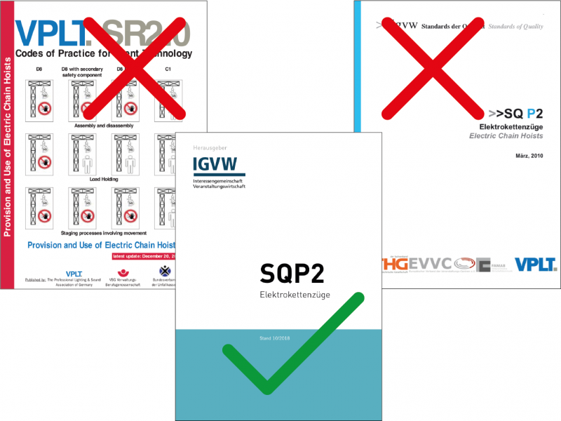
Figure 1 – 2018 official SQ P2 valid Code of Practice.
The D8+ chain hoist requirements changed during the years and today they are very different from the initial provisions; many users identify the D8+ chain hoist as an electric chain hoist with double brakes and a bigger chain (and other requirements they struggle to remember). In reality it is exactly those “other requirements” that make the electric chain hoist fulfil (or not) the D8+ condition.
Let’s analyse each requirement, what is still applicable and what is not, and how the provisions evolved during the last 15 years.
Load-bearing Lines
One of the most important requirements for a D8+ hoist was the size of the load chain. Chain hoist manufacturers select load chains such that the relation between the load chain MBF and the declared hoist rated capacity is above 4:1 in order to fulfil Machinery Directive requirements.
Basically, they apply the MD 2006/42/EC requirement as stated in point 4.1.2.4 which requires that lifting chains must have a working coefficient chosen in such a way as to guarantee an adequate level of safety. As a general rule, this coefficient is equal to 4.
An example of such approach would be a nominal size 8 mm load chain with a MBF of 80.4kN, for a hoist with a rated capacity of 1600 kg with 8 m/min max speed (the ratio also considers an average 20% of dynamic forces).
However, the CoP argued that the provision stated in the Machinery Directive concerning the coefficients to be applied for lifting people (the mechanical strength of load-bearing lines), should have also been applied for equipment left suspended above people. From MD 2006/42/EC, chapter 6.1.1: The working coefficients for components set out in sections 4.1.2.4 and 4.1.2.5 are inadequate for machinery intended for the lifting of persons and must, as a general rule, be doubled. This approach found its confirmation in national standards (BS 7905-1, DIN 56950, NEN 8020-10, etc.), which adopted a similar criterion in order to implement the passive redundancy in load-bearing elements.
In SQ P2:2010, the requirement stated that the operating coefficient of the load-bearing material (tensile strength) should be at least 10. At the time, the unofficial interpretation of the load-bearing material was referred to load-bearing lines as suspensions.
A couple of years before, in 2008, a CEN 15902-1:2008 technical document was published and stated that round wheel chains used to carry loads should meet the requirements for a safety factor of 8 at characteristic loading3. The concept of characteristic loading listed in the CEN 15902-1:20084 explained that the characteristic loading was the Safe Working Load5, plus the load carrying device (equal the system load), plus the dynamic forces.
SAFE WORKING LOAD (SWL)
+
WEIGHT OF LOAD CARRYING DEVICE
=
SYSTEM LOAD
+
DYNAMIC FORCES
=
CHARACTERISTIC LOAD
In the case of a D8+ chain hoist, with the intended use of keeping loads suspended above people, the dynamic forces were excluded from the characteristic load calculation due to the fact that in that condition, the load was at rest when people were allowed to be in the hazard zone. The conclusion was that for D8+ chain hoists based on CEN 15902-1:2008, a load chain static safety factor of 8:1 was sufficient.
In 2012, the DIN committee published a revised standard as a backbone for the BGV-C1 German regulations: the DIN 56950-1:2012. Concerning load chains, the DIN 56950-1:2012 matched the CEN 15902-1:2008 requirements and stated that round steel chains used to carry loads shall meet the requirements for a safety factor of 8 at characteristic loading6.
The SQP2:2010 requirement “operating coefficient of the load-bearing material of at least 10” therefore automatically became in conflict with the DIN 56950-1:2012 – 8 at characteristic load.
Nonetheless, this conflict was addressed and in the new SQ P2:2018, the provision is that a static coefficient (at rest) of 8:1 is sufficient for the load chain7. The CoP also states that during a lifting operation, it’s admissible for the safety factor of the chain to go below 8:1 since there are no people in the hazard zone during motion8.
The static coefficient (at rest) of a D8+ load chain is 8:1.
Group Mechanism
In 2005, table 3.1.1 of SR2.0 stated that the dimension of a D8+ chain hoist lifting mechanism should have been 2 x rated load and the group mechanism should have been minimum 1Bm. For dimension of the mechanism, the CoP referred to the gearbox and transmission elements and the 1 Bm class was related to the expected lifetime of the hoist9.
In 2010, the Engineering Requirements were renamed as Constructional Requirements and the “dimension of the motor” was set to double the lifting capacity.
The “dimension of the motor” created controversial opinions in the industry.
In the German version, the phrase Dimension des Triebwerks meant the dimension of the engine implied that the engine was both the gearbox and the electric motor, instead of only just the dimension of the motor. As a result, the requirement was that the entire “engine” should have been dimensioned to lift and support twice the characteristic load. The motor groups should have been at least at M3, and this requirement referred to FEM 100110.
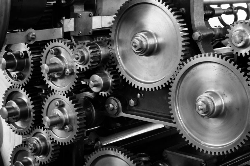
Figure 2 – Machinery mechanism and transmission gears.
In 2018, the Engineering or Construction requirement table disappeared and now there are other recommendations. As reported from the DTHG Technical Committee, “the chain hoist load-bearing parts need to be dimensioned to bear twice the characteristic load with the machinery at rest” [the German term ruhedn11 means resting, dormant, stationary]. “There is no demand for the D8+ hoist to be capable of lifting twice the characteristic load for a minimum of 400 hours as defined in EN 17206 or DIN 56950”.
When the chain hoist’s load-bearing elements are at rest, they should be able to keep suspended twice the chain hoist’s characteristic load.
Friction Clutch
The allowance of a friction clutch, its location and use has been a controversial point of the D8+ chain hoist requirement’s history.
In 2005, the SR2.0 table 3.1.1 stated Friction Clutch: no. Hence, a friction clutch was not permitted, unless it was located outside the load path when the electric chain hoist was disconnected from the power supply. Annex IV of SR2.0 explained in detail the position of the friction clutch for electric chain hoists. A friction clutch was allowed as an overload device and chapter 3.1.3 of SR2.0 also stated that the required shutdown condition could be fulfilled by means of a friction clutch.
NOTE: In 2005, the definition of friction clutch meant any friction coupling device installed between the lifting wheel and the load securing devices (the brakes).
In 2006, the EN 14492-2 was published, explaining the concept of a Direct Acting Rated Capacity Limiter12 (a friction clutch) as a differentiation from a Friction Coupling Device.
The international community debated for years about the provisions related to the clutch inside (or outside) of the load path (on the load side rather than on the motor side) and the definition of load modes, meaning the multi-hoist configurations had the potential of shifting loads in statically indeterminate scenarios.
The debate led the German technical community and the VPLT Chain Hoists Working Group to review the SR2.0, and issue a review in 2010: the IGVW SQ P2:2010.
In 2010, the provisions for clutches were that a slip clutch was allowed provided the conditions below were met:
- In statically determinate mode, the slip clutch was admissible on the load side, between the lift wheel and the brakes.
- In statically indeterminate mode, the slip clutch should not have been used as protection against overload and other means should have been used to cut-out the hoists in the group if 120% of the lifting capacity was reached.
The SQ P2:2018 states that direct-acting hoisting force limiters – no matter if they are inside or outside the load path – cannot be considered as overload devices for the D8+ chain hoist. Overload monitoring can only be achieved with Indirect Acting Capacity Limiters (sensors). The CoP also states that for D8+ hoists, adjustable direct acting force limiters should be set higher than the D8+ lifting capacity in order to be used as a lifting mechanism protective device rather than as an overload device.
Friction clutch, slipping clutch, friction force limiter, friction torque limiter and direct-acting capacity limiters are some of the many names you can call a friction coupling device.
Definitions are related to the engineering solution, the device’s function, its behaviour or simply what a device is normally called in the market.
It is important to analyse the definitions present in the original Standards in German language, and the related translation in English in order to make sure there are no misinterpretations.
SR2.0
Chapter 3.1.1: Rutschkupplung (translated: Friction clutch)
Annex IV: Anordnungen der Rutschkupplung bei Elektro-kettenzügen (translated: Position of the friction clutch for electric chain hoists)
SQ P2 2010
Chapter 4.1: Rutschkupplung (translated: Slip clutch)
SQ P2 2018
Chapter 4.2.1.2: Direkt wirkenden Hubkraftbegrenzer (translated: direct-acting force limiter device, or direct-acting load limiter device)
Chapter 4.2.1.1: Einstellbare direkt wirkende Hubkraftbegrenzer (translated: adjustable direct-acting force limiter device, or adjustable direct-acting load limiter device)
In all the definitions above the friction coupling device is intended as a torque limiter, which means an automatic device that protects mechanical equipment, or its work, from damage by mechanical overload.
Usually a torque limiter may limit the torque by slipping (as in a friction clutch or slip clutch) or uncouple the load entirely (as in a shear pin, used for other kind of machineries).
The fundamental point to be considered in order to understand what is allowed and what is not, is the intended use of the friction coupling device.
- Slip/friction clutches used to prevent the machinery from lifting more than the rated capacity are technically called friction torque limiters or rated capacity limiters.
These devices should be located outside the load path (limiting the force flow, on the motor side).
- Device used to protect the lifting mechanism from damages by mechanical overload, also when chain hoists are disconnected from the power supply, are friction coupling devices or mechanical protector devices.
These devices are allowed within the load path, but they need to be rated much higher than the permissible load capacity 13.
Adjustable friction clutches, slip clutches, direct-acting force limiters located outside the load path are allowed but they cannot be considered an overload protection device.
Friction coupling devices located inside the load path/force flow are allowed provided they are set higher than the D8+ rated capacity (EN 17206 provisions are that the setting should be at least twice the rated capacity).
Load Securing Devices
The benchmark requirement for a D8+ chain hoist has been the presence of two load securing devices, which means two mechanical devices that can bring the load to a defined stop and prevents unintentional movement (for example, brakes, dynamically irreversible worm gears, shut-off valves, etc.). The most common way to implement such a redundancy requirement is to fit the electric chain hoists with a double brake system, although there are chain hoists in the market which have one brake and one irreversible worm gear lifting mechanism.
SR2.0 in 2005 explained the requirement as such: Safety brake or, alternatively, dynamic transmission brake: 2 x, basically either “two electromagnetic brakes” or “one electromagnetic brake + one worm gear” (provided it was a self-sustaining worm gear with at least 85% of non-reversibility).
SQ P2:2010 read more or less the same: Numbers of brakes (or self-locking gearbox): 2.
SQ P2:2018 reiterates the same concept of the need for two load securing devices although it also states that an electric chain hoist equipped with double brakes and used for half of its capacity can be considered to meet the D8+ requirements14.
A D8+ chain hoist must be fitted with two load securing devices (for example brakes or dynamically irreversible worm gears).
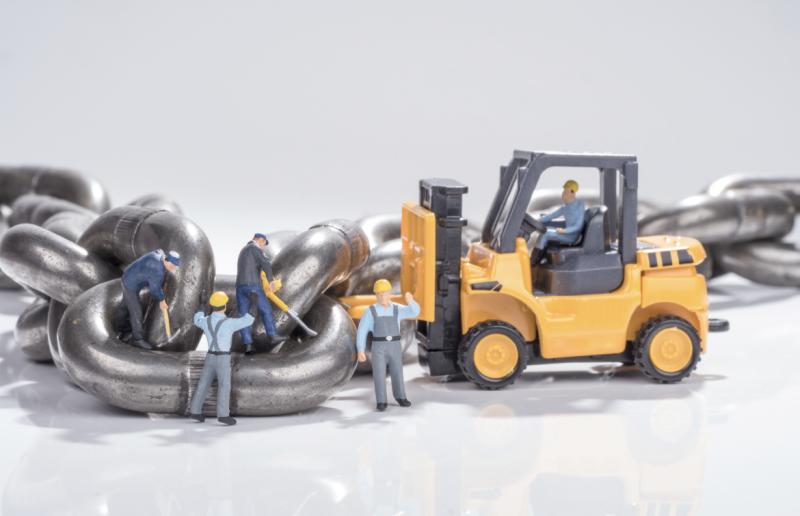
Figure 3 – How big does the chain need to be?
Load Monitoring
Monitoring the load, overload and underload conditions, has been a requirement for D8+ hoists since the beginning.
In 2005, SR2.0 stated: Overload Monitoring: Shutdown and Underload Monitoring: no.
The requirements were mainly referring to the friction clutch.
In 2010, the requirement was updated to: Overload Monitoring: Protection against overloading and Underload Monitoring: no.
In 2018, the concept has been better explained, therefore, chain hoists with built-in friction coupling devices rated at 200% of the rated capacity, will be suitable to become D8+ hoists, provided they are always put into service together with a load monitoring system capable to shut-off the hoist in motion once they reach 120% of the rated load. The load monitoring system will act as an Indirect Rating Capacity Limiter, suitable for overload protection, and the protector kit will be considered an admissible friction coupling device.
D8+ chain hoists must be fitted – or put into service – with an overload system capable to shut down all the hoists in motion if an overload condition of 120% occurs. In other words, the D8+ chain hoist’s machinery movement should be stopped when the load exceeds 1,2 times the characteristic load.
Other Requirements
Limit Switches.
SR2.0 stated: Emergency Limit Switch: no – Limit Switch: no.
SQ P2:2010 stated: Emergency Limit Switch: no – Operating Limit Switch: possible. Although the emergency limits were not required, the operational limits were possible.
In the SR2.0, the interpretation of the condition for the “Limit Switch: no” could have been misleading and indicated that the limits switches were not acceptable, rather than not required.
The SQ P2:2010 allowed the presence of the limit switches although they were not necessary, but the provision was still misleading. The same wording has also been used to describe the underload requirement: Underload Monitoring: no. Common sense suggests that the requirement is not necessary rather than forbidden.
Limitation of travel via limit switches is required only where overtravel can result in mechanical damage or failure.
Underload monitoring is not a necessary requirement for D8+ chain hoists.
And tomorrow?
There are a lot more details included in the SQ P2:2018, such as the importance of a risk assessment as a tool to deviate from the CoP requirements and the examination of how a “D8+ condition” can be reached from a system point of view rather than using already compliant D8+ machinery.
We believe that the clarifications contained in this case study are sufficient to allow manufacturers and users to understand the D8+ scenario a little bit better.
If you ask to yourself, for how long the D8+ chain hoist denomination will remain alive within the market, we may say probably not for long. Apparently, new European guidelines will replace this and other national regulations very soon, bringing clarity and common approaches and introducing even a simpler and rational denomination for all machineries used within the entertainment industry. However, the D8+ chain hoist still serves a very important part of the industry and riggers of any part of Europe (and abroad) rely on this affordable type of machinery for their daily installation.
Tomorrow these chain hoists may be called different names, but the long journey of the D8+ hoist is not in vain; this hybrid equipment, created as compromise between industrial and stage machineries, has been the bridge to fill in the gap between two markets that are very different from each other.
And when a void between industries is filled, the pattern toward a better understanding of its challenges… is already drafted.
.
1. The German word for “Code of Practice” is “Standard’. The German word for “Standard” is “Norm”.↩
2. VPLT. SR2.0:2005 | Code of Practice for Event Technology – Provision and Use of Electric Chain Hoists.↩
3. EN 15902-1:2008 Chapter 5.4.2.2 Chains.↩
4. CEN 15902-1:2008 Chapter 3.2 Loads and forces, Table 1.↩
5. CEN 15902-1:2008 Chapter 3.2.6 SWL is maximum load (mass) as assessed by a competent person which an item of lifting equipment may raise, lower or suspend under the particular service conditions.↩
6. DIN 56950-1:2012, Chapter 5.2.2.2 Chains.↩
7. Das Tragmittel (Kette) besitzt für den Zustand „ruhend“ einen Betriebskoeffizienten von 8.↩
8. Für den Zustand „in Bewegung“ sind niedrigere Betriebskoeffizienten zulässig, da sich in diesem Zustand keine Personen im Gefahrenbereich aufhalten dürfen.↩
9. See the article “The life expectancy of a chain hoist”.↩
10. Booklet 2, chapter 2.1.3.1, stating that individual mechanisms as a whole are classified in eight groups, designated by the symbols M1, M2, M3……M8, on the basis of ten classes of utilisation and four classes of loading spectrum.↩
11. Für den Zustand „ruhend“ sind die Betriebskoeffizienten aller sich im Kraftfluss befindlichen Elemente des Elektrokettenzuges bekannt und mindestens für die doppelte Tragfähigkeit des D8 Plus.↩
12. EN 14492-2:2006 – Chapter 5.2.2.2.2.↩
13. They need to be constructed in such a way that in the case of a failure of plastic or rubber parts, there is a positive engagement by metal parts. EN 14492-2 | Couplings.↩
14. SQP2:2018 Chapter 4.2.1.2, first paragraph.↩