This article examines the role of brake microswitches in the event industry, focusing on their function as positional sensors within safety-critical machinery. While these switches can be used to provide feedback to control systems, they have significant limitations that must be understood to ensure comprehensive safety.
The Basics of Microswitch Integration
The modern event production environment relies on a sophisticated ecosystem of automated machinery, including electric chain hoists, winches, stage lifts, and mobile scenic wagons. In nearly all of these systems, the failsafe spring-applied brake is the most critical safety component. The integration of a microswitch is intended to transform this passive mechanical device into an active, monitored element of the overall safety control system.
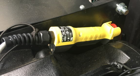
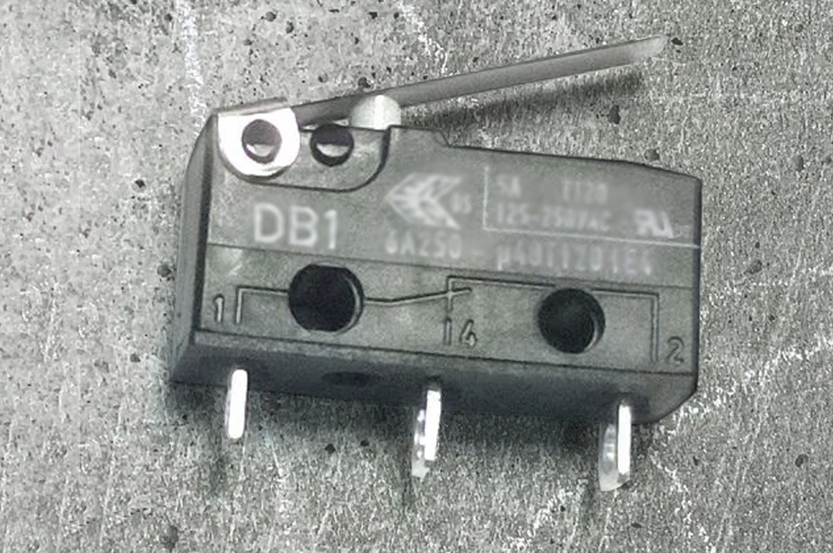
The primary function of the brake microswitch is to provide direct, physical confirmation of the brake’s mechanical state to a central controller, such as a Programmable Logic Controller (PLC). The switch is physically mounted on the brake assembly to detect the movement of the brake’s armature plate. The operational logic is straightforward:
- Brake Engaged: When power is removed from the brake’s electromagnetic coil, powerful springs force the armature plate onto the friction disc, engaging the brake. This mechanical movement simultaneously actuates the microswitch, which sends a signal to the PLC.
- Brake Disengaged: When the PLC commands the brake to release, it applies power to the coil, creating a magnetic field that pulls the armature plate away from the friction disc. This movement allows the microswitch’s actuator to return to its resting position.
The control system might be programmed to use this signal to verify that the brake is fully released before applying torque to the motor. This prevents the motor from fighting against a closed brake—a condition that can lead to motor overheating, drive faults, or severe mechanical strain.
Limitations and Functional Safety Considerations
While a passive, failsafe device is inherently safe when unpowered, a brake with a microswitch becomes an active device, with power supplied permanently. Therefore, it must become part of the functional safety analysis. If not considered properly, the switch itself could introduce new failure modes and compromise the braking system.
A crucial distinction is that the microswitch detects the mechanical position of the brake’s components, not the performance or force of the brake itself. It can confirm that the brake armature has moved away from the disengaged position, but it cannot verify the amount of clamping force being applied or the friction generated. Nor can it determine if the brake has moved to a fully and effectively engaged position. Therefore, its most reliable function within safety logic is to confirm that the brake has been successfully released, allowing the control system to safely apply power to the motor without opposition.
While a motor running against a closed brake can cause long-term equipment failure, it does not typically represent an immediate danger of a dropped load. Furthermore, this detection method is primarily useful for fixed-speed machinery without overcurrent protection. Modern machinery equipped with current-sensing mechanisms, either through an inverter (VFD) or other devices, can already detect the overcurrent condition caused by a motor fighting a closed brake, making the microswitch’s feedback for this specific scenario redundant.
Operational Failure Modes in Touring Machinery
While a microswitch in a fixed industrial installation may operate reliably for decades, its life in touring machinery is far more perilous. Touring equipment is subjected to a punishing lifecycle of road transport, manual handling, and exposure to harsh environments. Consequently, the failure profile is dominated by environmental and handling-induced factors, not its rated operational cycle count.
Failure modes specific to this application include:
- Mechanical Failure from Vibration and Shock: Constant vibration during transport can induce metal fatigue in the switch’s internal spring, causing it to fracture or shift its actuation point. Vibration can also loosen electrical connections, while impacts during loading can cause direct physical damage to the switch housing or actuator.
- Electrical Failure from Environmental Ingress: Touring equipment is frequently exposed to humidity, condensation, and moisture. If a microswitch is not adequately sealed, moisture can penetrate the housing and cause corrosion on the contact surfaces, corrupting the signal. Contamination from dust or theatrical fog can also cause the mechanism to stick.
- Premature Wear and Misalignment: If the brake or motor assembly is misaligned during rigging, the actuating component may strike the switch with improper force or at the wrong angle, placing excessive stress on the actuator and leading to premature mechanical failure.
To mitigate these risks, equipment manufacturers must consider if such a device is suitable for the rigors of touring. Drawing lessons from the automotive sector, which faces similar challenges, is key. Specifying automotive-grade microswitches with high Ingress Protection (IP) ratings (e.g., IP67), robust construction, and a wide operating temperature range is a critical strategy for enhancing reliability.
Common Cause Failures Undetectable by Positional Switches
The microswitch has a fundamental limitation: it is a positional sensor, not a performance sensor. It can report that the brake’s mechanical components have moved, but it is completely blind to the effectiveness of the braking action. This gap creates a significant blind spot where a brake can fail in a manner that is entirely undetectable by the control system.

The most insidious brake failures are those where the monitoring system reports a normal state while the brake itself is compromised. These often arise from a single root cause that degrades performance without impeding the mechanical movement the switch detects.
- Contamination of Friction Surfaces: This is the most critical undetectable failure mode. A leak from a gearbox or motor can contaminate the brake pads and disc with oil or grease, drastically reducing the coefficient of friction. The brake will still engage mechanically, and the microswitch will send a “Brake Engaged” signal. The controller, believing the load is secure, will proceed, but the brake’s actual holding torque may be a fraction of its design capacity, potentially allowing a load to slip in a catastrophic failure.
- Overheating and Brake Fade: Frequent or heavy braking can cause overheating, leading to “brake fade” or permanent “glazing” of the brake pads, where the surface becomes smooth and ineffective. The mechanical actuation is unaffected, and the microswitch reports that the brake should be engaged, but the compromised friction surfaces cannot provide the necessary holding force.
- Progressive Mechanical Wear: Brake pads and discs are consumable components. A microswitch cannot determine if the friction material has worn to a dangerously thin level. It only confirms that the mechanism has traveled to its end stop, regardless of whether there is sufficient pad material left to generate the required clamping force.
These scenarios create a dangerous disconnect between the system’s perceived state and its actual capability. This false sense of security is the single greatest risk associated with an over-reliance on automated positional monitoring.
Mandatory Physical Inspections are Non-Negotiable
The analysis of the microswitch’s capabilities and limitations leads to an unequivocal conclusion: automated monitoring is a nice-to-have feature, but can never be a replacement for, a rigorous regimen of physical inspection and maintenance performed by competent personnel. Although a brake microswitch can be part of the diagnostics from a Brake Control safety circuit, it is not a safety function, it is not a safety device, and it doesn’t perform any additional functions different from a brake contactor switch.
A technician’s visual inspection can immediately spot the tell-tale signs of a fluid leak, oil contamination, or severe overheating. A functional test can reveal an unresponsive brake, while audible cues like grinding can signal excessive wear long before total failure. Finally, only direct measurement with calipers can confirm that brake pad thickness and disc wear are within the manufacturer’s specified safety tolerances.
Always follow the period of inspections and testing instructions detailed by the manufacturer and national regulations, whichever is the most frequent and restrictive. These inspections exist precisely because a machine’s condition can degrade in ways not captured by its own control system, making physical verification essential.