Automation, Video and Lighting will often share the same generator or transformer when touring. Yet, if the load is unbalanced, unexpected flickering lights and spurious drive trips will become a part of the show.
As funambulists use the centre of mass to maintain their balance and prevent a fall, three-phase power systems also use the frequency offset between their phases to share the load and keep the circuit balanced. Thus, the current flows from one or two of the phases and returns to its source from the remaining phases just as some funambulists would use a pole to walk on a rope. In a perfect world, the pole would not be necessary; however, it helps maintain the balance when environmental or unexpected situations occur.
For this reason, the Neutral Wire on a three-phase system plays a similar role, it is not required, but when the lines are unexpectedly unbalanced the Neutral Conductor will help by carrying the excess of the load back to the source.
.

Figure 1: Three-phase signals
Three-Phase Power
Three-phase electric power is a common method of alternating current and it is the most common method used to transfer power. It is also used to power motors and other heavy loads.
Three-wire circuits use less conducting material and are usually a cheaper way to transmit the same amount of electrical power than an equivalent 2-wire single-phase circuit.
Star-points are a construction where all phases meet at a central point. In this kind of construction, the phases naturally tend to achieve a natural balance in the centre. Electrical leakage and poor electrical load distribution are usually the key players that pull the star-point away from the centre 0 V mark or Neutral Point. Additionally, an optional Neutral Wire allows the three-phase system to supply a lower voltage—across phase and neutral—so that it can support domestic single-phase equipment.
3-Wire Connections
Three-phase systems are designed to cancel the currents of one phase to another. This quality allows for the copper wiring to be saved with the removal of the Neutral Conductor.
If the star-point of a load—for example a 3-wire hoist—is unbalanced or is not connected at the source, then the phase voltage does not remain the same across each phase. The potential of an isolated star-point is always changing and is therefore called a Floating Neutral.
4-Wire Connections
Three-phase wiring with a Neutral Wire is considered to be a 4-wire system. These systems allow for three-phase higher voltage loads and single-phase lower voltage loads to be used. When single-phase loads and three-phase loads are used in a system together it is known as a mixed load three-phase system.
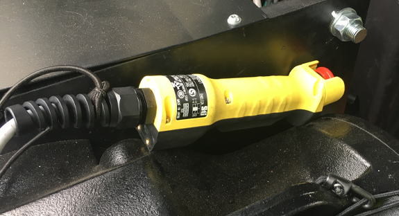
Most equipment in the event industry is single-phase and we can identify it by finding a 2-wire plus earth connector in either a domestic plug format or an industrial format. However, if the generator or transformer has a three-phase output, the equipment will be distributed across the three lines, L1, L2 and L3, and use a common neutral for the current return. Motors and inverters will generally use a three-phase wiring feed.
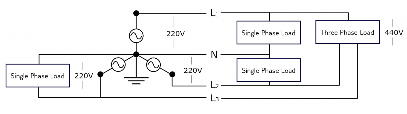
Figure 2: Healthy three-phase system with mixed loads
Balanced or Unbalanced
All of the current entering a system must return to its source. This is known as Kirchhoff’s Current Law. In a balanced system, one phase should match the other two phases and result in no current going through the Neutral Wire. In an unbalanced system, the current must flow through the Neutral Wire, so that the balance is maintained.
The Neutral Wire should never be connected to Ground except at the power source, where the neutral is initially grounded at the generator or the transformer. Grounding the Neutral Point in a three-phase system with heavy leakage—like an inverter system—helps stabilise the phase’s voltage. A non-grounded neutral is sometimes referred to as a Floating Neutral and has very few limited applications.
Floating Neutral
The Neutral Conductor can become a Floating Neutral in an installation when the Neutral Connection between the machine and the generator is broken or non-existent, or when the Neutral Point at the generator loses its reference ground.
A Floating Neutral might cause the circuit to elevate to a maximum voltage of the Phase RMS when measuring it to Ground. This often results in a difference of hundreds of volts between the Neutral Wire and Ground causing damage to the connected equipment and create voltage that is hazardous to touch on the machinery body.
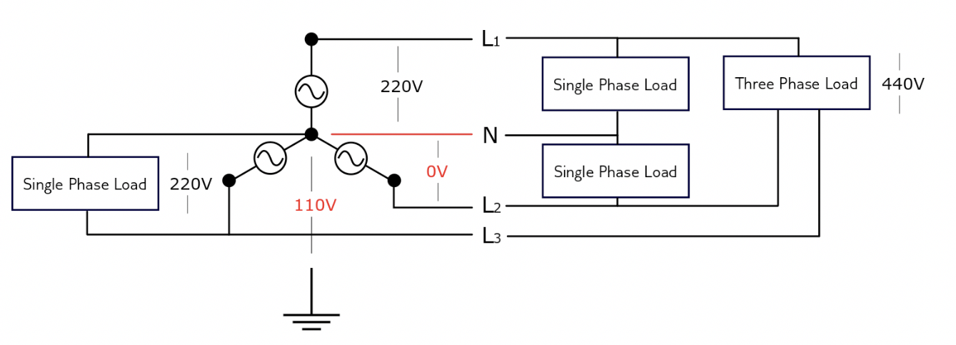
Figure 3: Floating Neutral condition – No effect on three-phase devices, single phase devices on L2 have no voltage
Voltage Measurement between Neutral to Ground
Low Reading
When the system is loaded, the Neutral-to-Ground voltage on the machinery-end is low—usually around 2 V—then the system is healthy.
High Reading
A high Neutral-to-Ground voltage reading—usually over 5 V—could indicate the system is overloaded or that the system has a Floating Neutral.
Zero Reading
A Neutral-to-Ground voltage reading slightly over zero near the machinery is normal in a loaded circuit.
If the Neutral-to-Ground voltage reading is stable and close to zero, there might be a short-circuit between the Neutral and the Earth wires at the machinery-end.
Neutral-to-Ground bonds outside the generator should be removed to prevent return currents flowing through the Ground (Earth) wiring.
Possible Causes of Floating Neutrals in the Event industry
At the Three-Phase Generator or Transformer
Some generators or transformers are not set with a Grounded Neutral by default since this is a configuration option. So, when installing the transformer or generator, grounding the machine is one of the most important steps before powering it up. If the Neutral Point is grounded to Ground, but Ground is not properly grounded, the Earth Wire and the Neutral Wire will both float at hundreds of volts of potential, producing a dangerous hazard to touch the equipment’s metal parts. Some installations will experience overvoltage while some will experience undervoltage.
Overloading and Load Unbalancing
Poor load distribution could be one of the reasons of failure. The installation should be properly designed so that minimal current will flow into the Neutral Wire.
In a perfectly fully-loaded balanced system the Neutral Wire will see no current. And in an overloaded unbalanced installation, a lot of current will flow through the Neutral Wire, which might not be able to cope with it.
Shared Neutrals
Some three-phase installations are wired so that some parts of the installation share the same Neutral Wire when the three phases are separated into single-phase circuits.
The idea is to duplicate on the single-phase circuit level from a 4-wire system. On the paper, in an ideal three-phase system, only the unbalanced current will return to the Neutral Wire, which allows for a single Neutral Wire to serve the three phases. However, when the three-phases are split into three-single-phase systems at a distribution unit, a single Neutral Wire between the Neutral Point and the distribution unit has to cope with the load of three individual systems. The load from the three single-phase circuits cannot be balanced between the phases as it would be in the case of a three-phase system and must return to the Neutral Point at the generator or transformer.
Shared Neutrals are not only a safety problem because of the overheating of undersized Neutral Wires, but also because the extra current passing through the Neutral Wiring creates a Neutral-to-Ground voltage that is hazardous to touch.
Installation and Maintenance
Usually a Low Voltage network seems simple enough that it does not gain much attention from the maintenance staff. Loose or inadequate tightening of the Neutral Conductor will reflect on a Floating Neutral and spurious flickering and inverter trips.
Poor installation workmanship and technical staff are another reason for failure.
Conclusion
To prevent and eliminate electrical problems in tours, temporary and fixed installations, we must understand that three-phase systems are never plug and play, and that we must try to isolate mixed-load circuits that are not designed to be plugged-in together. This statement is a must when the unbalancing is very difficult to estimate or when it might unexpectedly change during the show. A good example of this is when a huge section of lighting is plugged into different single-phase circuits that are randomly turned on and off. Not balancing the lines properly may result in the circuit overloading and a fire risk.
Nevertheless, we must assign a higher priority on the wiring layout and the equipment maintenance on fixed and temporary installations. We must ensure that electrical installations fulfil the requirements under the Low Voltage Directive 2014/35/EU. We must also reduce the risk of Floating Neutrals by checking that all Neutral Connections are tight, the connectors are plugged properly, and ensure that the transformers or generators are properly configured and grounded.
.